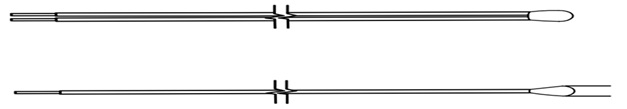
BMS Temperature Sensor

Applications
Measure cell or coolant temperature to protect cells
Measure cell or coolant temperature to protect cells
Features
High Accuracy & Stability
Fits inside battery modules without affecting space or thermal characteristics.
Fast Thermal Response
Options
Operating Temperature
–40°C to +125°C / up to +150°C for high temp variants
Sensor Type :
Bead / Disc / Epoxy coated / Glass encapsulated / Probe type
Encapsulation
Epoxy, resin, or glass bead; insulated for battery pack insertion
Leads
Flexible PTFE or silicone-insulated wires; SMD pads for PCB-mounted battery monitoring
Mounting Options
Embedded between cells, attached to cell surface, or integrated into BMS PCBs
Rated Temperatures and Dissipation Factor
Lower Temperature : -40°C
Upper Temperature : 140°C
Max Permissible Power at 25°C : 60 mW
Resistance Tolerance (ΔR/RN ) : ±0.5%, ±1%, ±2%, ±5%
Rated Temperature (TN) : 25°C
Electrical Data (Resistance and Beta Values)
| Resistance At 25°C (Ω) | Beta Value (25/85) (K) | |||
| 2000 | 3540 | |||
| 2057 | 3540 | |||
| 2800 | 3900 | |||
| 3000 | 3977 | |||
| 4700 | 3977 | |||
| 5000 | 3977 | |||
| 10000 | 3977 | |||
| Resistance At 25°C (Ω) | Beta Value (25/85) (K) |
| 20000 | 4000 |
| 30000 | 4050 |
| 47000 | 4100 |
| 49300 | 3960 |
| 50000 | 4100 |
| 100000 | 4400 |
| 170000 | 4250 |
Reliability Data
| Test | Standard | Test Conditions | Change In R | Remarks | |||||||||||
| Storage in dry heat |
IEC 60068-2- 2 | Storage at upper category temp T: 100°C t: 1000 h |
<2% | No Visible Damage | |||||||||||
| Storage in damp heat, steady state |
IEC 60068 – 2- 78 |
Temp of air:40 °C Relative humidity of air: 93 % Duration: 56 days |
<2% | No Visible Damage | |||||||||||
| Rapid temperature cycling |
IEC 60068 – 2- 14 |
Lower test temp:– -30°C Upper test temp: 150°C Time to change from lower to upper temperature: <30 s Number of cycles: 1000 Medium: air |
<2% | No Visible Damage | |||||||||||
| Storage in coldness |
Storage at lower category temp T: -30 °C t: 1000 h |
<2% | No Visible Damage | ||||||||||||
| Vibration resistance |
IEC 60068-2-6 | Frequency range: 5 to 500 Hz Amplitude: 7.5 mm, 2 g Duration: 3 x 8 h |
<3% | No Visible Damage | |||||||||||
| Long-term stability (empirical value) |
Temperature: 200 °C t: 10000 h |
<3% | No Visible Damage | ||||||||||||
| Voltage proof Test | 1250 V AC, 1 s | <3% | No flashover | ||||||||||||
| Insulation test | The sensors are placed in a vessel containing metallic balls of 1 mm diameter (with total immersed head). The applied voltage is 100 V DC. |
Above 1000 MΩ |
|||||||||||||
| 103 – 10K | R2 – 2% | E01- Blue Epoxy Powder Coating | K- PTFE Multi strand copper wire | H- AWG 26 | 100MM | B(25/85) |
| R- 1% | E03 – Epoxy Dip Coating | AA- FEP Multi strand copper wire | F- Awg 28 | 500MM | ||
| R3 – 3% | E02- Black Epoxy Powder Coating | K – AWG 24 | 450MM | |||
| R5 – 5% | M – AWG 22 | 440MM |
STLT *** R# E%% @@ $$$ &&&&
*** = Resistance Value at 25°C (e.g. 102- 1000Ω, 201 – 200Ω, 103 – 10kΩ)
# = Resistance Tolerance (eg. R1 – ± 1%, R5 – ±5%)
%% = Encapsulation (eg. E01 – Epoxy Powder Coated (Blue))
@@ = Type of Lead (eg. GC, G – Single strand Nickel Wire(Silver Plated) & C – 30 AWG)
$$$ = Total Length in mm (eg: 250 – 25mm Length, 401 – 400 mm Length)
&&&& = Beta Value (eg:3977K, 3830K)