Battery Cooling System Temperature Sensor

Applications
Measure cell or coolant temperature to protect cells, control charging/discharging,
Used directly by the BMS for thermal monitoring (cell-level and pack-level), thermal runaway detection thresholds, and charge-rate control.
Features
High Accuracy & Stability
Fast Thermal Response
low cost, easy to attach to cell surface or pouch using adhesive
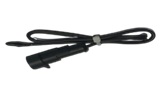
Sealed/overmolded sensor assemblies with connectors — for harsh environments, IP-rated packs, and easy harnessing in automotive harnesses.
Fits inside battery modules without affecting space or thermal characteristics.
Low Self-Heating
Options
Rated Temperatures and Dissipation Factor
Lower Temperature : -40°C
Upper Temperature : 140°C
Max Permissible Power at 25°C : 60 mW
Resistance Tolerance (ΔR/RN ) : ±0.5%, ±1%, ±2%, ±5%
Rated Temperature (TN) : 25°C
Electrical Data (Resistance and Beta Values)
| Resistance At 25°C (Ω) | Beta Value (25/85) (K) | |||
| 2000 | 3540 | |||
| 2057 | 3540 | |||
| 2800 | 3900 | |||
| 3000 | 3977 | |||
| 4700 | 3977 | |||
| 5000 | 3977 | |||
| 10000 | 3977 | |||
| Resistance At 25°C (Ω) | Beta Value (25/85) (K) |
| 20000 | 4000 |
| 30000 | 4050 |
| 47000 | 4100 |
| 49300 | 3960 |
| 50000 | 4100 |
| 100000 | 4400 |
| 170000 | 4250 |
Reliability Data
| Test | Standard | Test Conditions | width=”128″>Change In R | Remarks | |||||||||||
| Storage in dry heat |
IEC 60068-2- 2 | Storage at upper category temp T: 100°C t: 1000 h |
<2% | No Visible Damage | |||||||||||
| Storage in damp heat, steady state |
IEC 60068 – 2- 78 |
Temp of air:40 °C Relative humidity of air: 93 % Duration: 56 days |
<2% | No Visible Damage | |||||||||||
| Rapid temperature cycling |
IEC 60068 – 2- 14 |
Lower test temp:– -30°C Upper test temp: 150°C Time to change from lower to upper temperature: <30 s Number of cycles: 1000 Medium: air |
<2% | No Visible Damage | |||||||||||
| Storage in coldness |
Storage at lower category temp T: -30 °C t: 1000 h |
<2% | No Visible Damage | ||||||||||||
| Vibration resistance |
IEC 60068-2-6 | Frequency range: 5 to 500 Hz Amplitude: 7.5 mm, 2 g Duration: 3 x 8 h |
<3% | No Visible Damage | |||||||||||
| Long-term stability (empirical value) |
Temperature: 200 °C t: 10000 h |
<3% | No Visible Damage | ||||||||||||
| Voltage proof Test | 1250 V AC, 1 s | <3% | No flashover | ||||||||||||
| Insulation test | The sensors are placed in a vessel containing metallic balls of 1 mm diameter (with total immersed head). The applied voltage is 100 V DC. |
Above 1000 MΩ |
|||||||||||||
| STTS | 103 | R1 | E03 | V | P | 361 | 3977 | C45 |
| 103 – 10K | R2 – 2% | V- PVC Twin Parallel Copper Wire | P- AWG 20 | 360MM | B(25/85) | C45 – 282104-3 Ambient Connector(Sealed) | ||
| R- 1% | E03 – Epoxy Dip Coating | T- PVC Multistrand Copper Wire | H- AWG 26 | 100MM | C16 – HR2522J-2Y | |||
| R3 – 3% | N – XLPE Multistrand Copper Wire | K – AWG 24 | 500MM | C1 – XHP 2 Pin Connector | ||||
| R5 – 5% | M – AWG 22 | 450MM | C6 – JST VHR 3N | |||||
| 440MM | C22 – PAP-02 V – S (JST) |
STLT *** R# E%% @@ $$$ &&&&
*** = Resistance Value at 25°C (e.g. 102- 1000Ω, 201 – 200Ω, 103 – 10kΩ)
# = Resistance Tolerance (eg. R1 – ± 1%, R5 – ±5%)
%% = Encapsulation (eg. E01 – Epoxy Powder Coated (Blue))
@@ = Type of Lead (eg. GC, G – Single strand Nickel Wire(Silver Plated) & C – 30 AWG)
$$$ = Total Length in mm (eg: 250 – 25mm Length, 401 – 400 mm Length)
&&&& = Beta Value (eg:3977K, 3830K)